Manufacturing Tool and Workflow Redesign | Engineering Tool
Boosting production output 6x and eradicating human errors with a new system that people enjoy using
An important new IoT computing device was being launched soon, and we had 3 months to replace the obsolete manufacturing systems used to produce these devices and make them more efficient and reliable to ensure optimum output.
About the product
The manufacturing line produces mini computers that serve as networking devices for various industrial and commercial applications, such as enabling any machine in a factory to connect to the internet.
This means that each device must be uniquely configured during production to seamlessly integrate with the customer’s existing infrastructure.
My role
As the sole designer for this project, I was responsible for planning and executing research; designing the systems, UX, and UI; and guiding the team through the process.
Step 1: Understand the problem
We began by visiting the manufacturing facility to observe how technicians work.
I studied their environments, behaviours, pain points, and needs to ensure that our solutions can empower technicians to perform at their best.
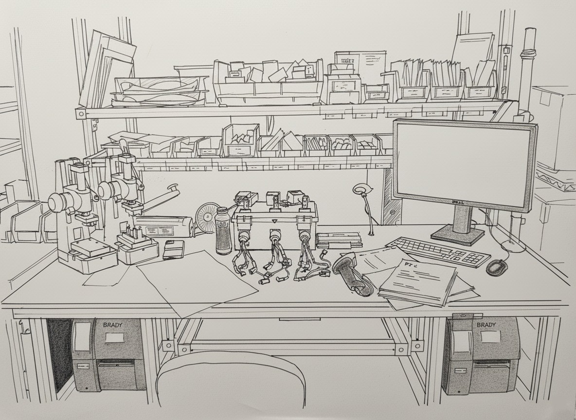
Illustration of a real technician’s workstation in the manufacturing facility
🎯 Defining our goals
We held regular team meetings with stakeholders and subject matter experts from the manufacturing facility.
Reduce manufacturing costs by reducing production time.
Reduce manufacturing errors due to human error.
Increase production output.
💡 What we learned
Technicians have workstations with a PC, handheld scanner, programming bays where the devices plug into for configuration, label printers, and paper purchase order forms, among many other things.
Many techs seldom use the system which requires a lot of training and retraining.
The work, happening 24 hours a day, is manual-intensive and requires a lot of concentration.
Understanding what technicians expect
Technicians utilised the legacy “BrainWasher” software to configure (program) blank IoT devices on programming bays and a PC at their workstations. The system was over a decade old, caused numerous human errors, and couldn’t support new devices.

The default empty state shows various settings that adapt based on the context.

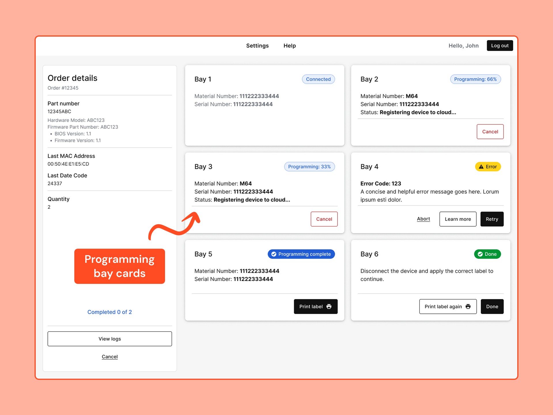
After testing, Bay 3 will configure a new IoT device that will be plugged into the physical programming bay, connected by numerous wires.
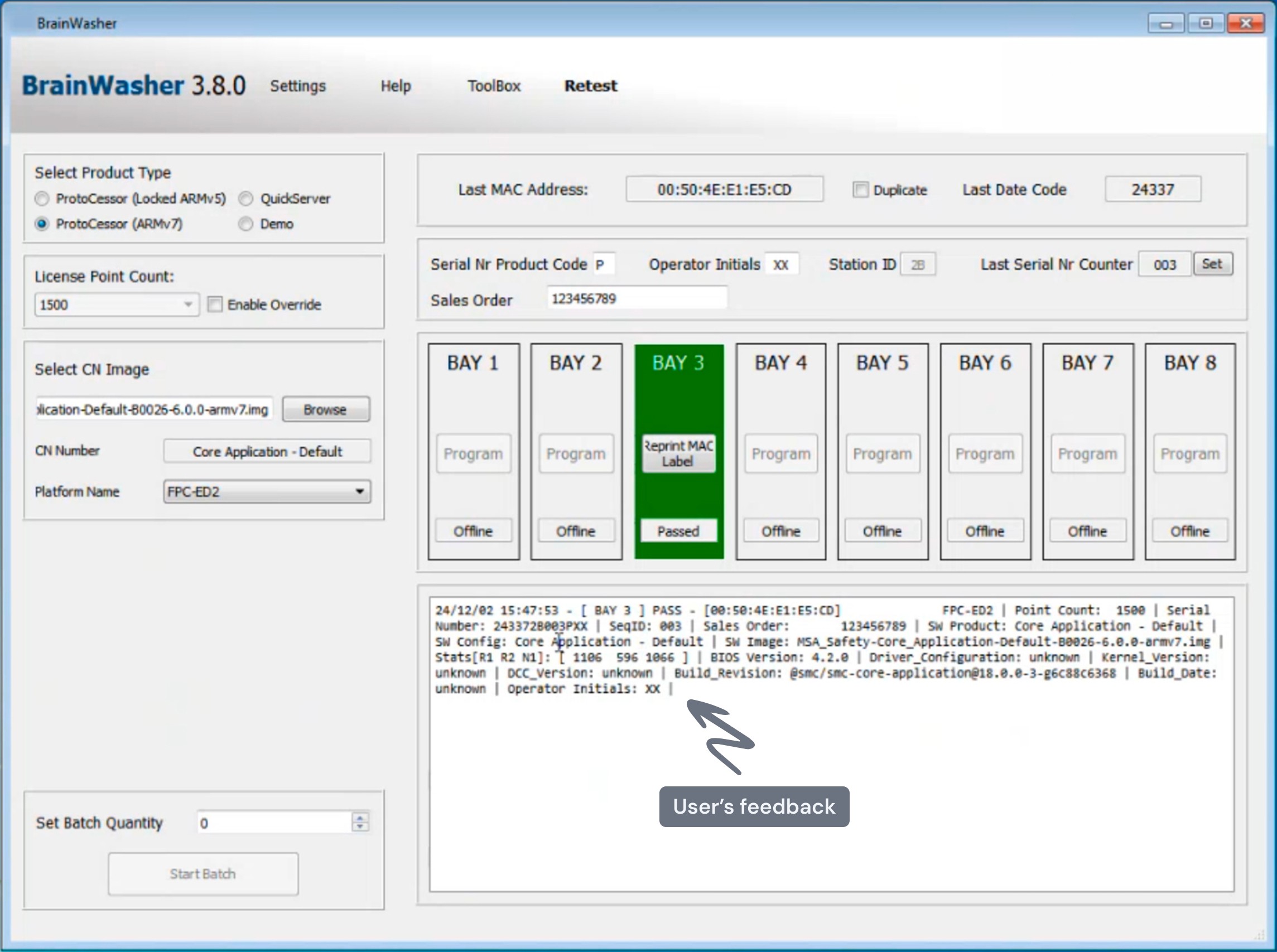
Bay 3 has successfully completed programming, and the device label will automatically print, which a technician will then apply to the casing.
Step 2: Process optimization
I carefully analysed the complex configuration workflows by conducting workshops with subject matter experts. These workshops allowed us to delve into both the technical and human aspects of the system, uncovering opportunities to improve its efficiency and reliability.
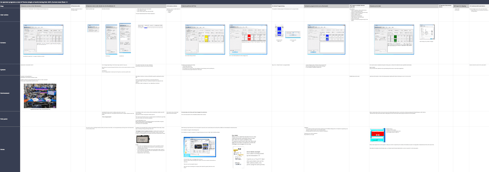
Task flow analysis
Major issues
Solutions
The most error-prone and tedious step was manually setting up a big list of confusing settings for each order.
“There are over 700 folders. This is a big pain point.” - User
Auto-populating the system with the configuration settings by using the handheld scanner that’s at each desk to quickly scan barcodes that are already on their purchase orders.
It was very hard to ensure that the unique labels (with essential information) for each device get applied to the correct device. The system automatically printed everything, which caused major inefficiencies and human errors.
I redesigned the printing workflow by putting the user in control of the printing process and removing the pain points and system bugs that hindered users.
Technicians didn’t use the batch configuration feature and usually programmed one device at a time, dramatically raising production costs.
I made batch programming more discoverable and addressed users’ concerns regarding the label printing process that hindered them from doing batch configurations.
The legacy interface was very cluttered and unintuitive, leaving many important features completely undiscoverable to all users.
"We were never trained..." - User
My goal was to simplify, making important features more salient, while ensuring easy change management by keeping the layout familiar to current users.
Step 3: Designing a tool that supports users and scales with technical requirements
Our users, the technicians, work in a high-pressure environment; they are constantly moving between tasks for hours while keeping lots of details in their heads. To help them focus on what matters and prevent costly mistakes, I designed the UI to be highly 'glanceable.'
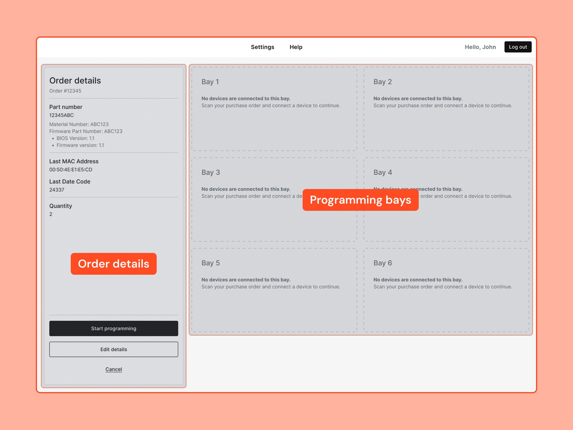
I kept the interface familiar to current users by keeping the navigation and screen layout similar to the legacy system.
I emphasised the programming bays so that users can easily focus on the most important information while they're running around.
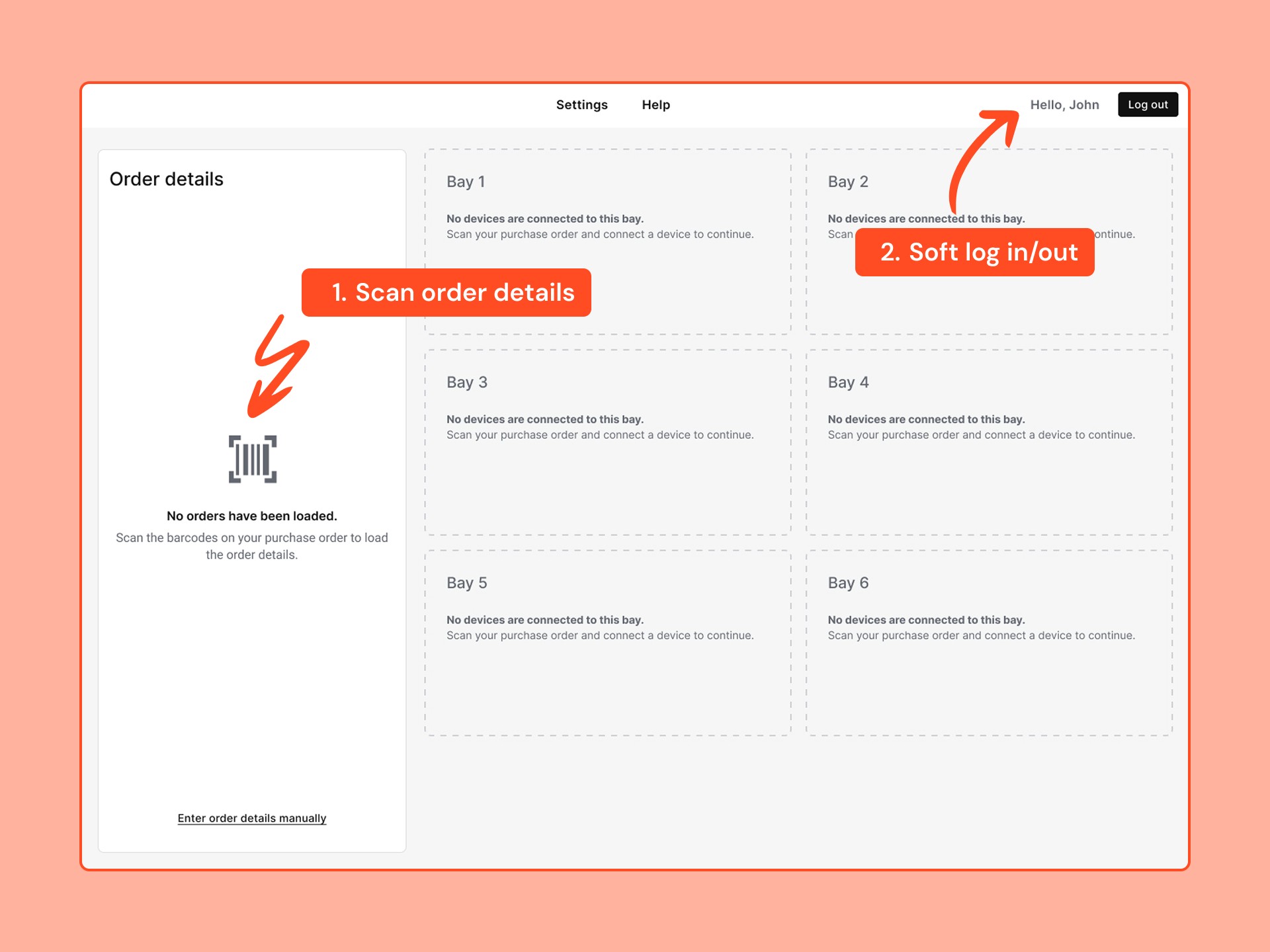
All the tedious, error-prone settings are gone! Technicians simply need to scan 2-3 barcodes on their purchase order forms using a handheld scanner in order to populate the system.
Techs can quickly log in/out by scanning their ID badge or by entering a code manually at the start of their shift to keep track of their work.
Configuration process
After technicians load the order details, they will physically connect the blank IoT devices to the programming bays using several wires.
Then, the system will automatically detect the device and initiate the configuration process.
Each bay card now holds significantly more information about the device and the status of each step, enabling technicians to clearly track the process of each bay. This enhanced clarity, coupled with automation, significantly boosts production output.
Lastly, after a device has been configured, the technician will click on the print label button and disconnect the device for packaging. This control ensures that technicians can always identify which label corresponds to which device.
🚧 Some challenges we faced
Since we had to connect to a complex manufacturing plant with numerous systems, we faced several challenges that required us to remain closely collaborative as a team.
Initially, scanning barcodes appeared to be a straightforward solution. However, we had to collaborate with multiple departments within the organisation to ensure that we could populate the barcode system with all the necessary details.
Software engineering resources were very limited, so we had to make several compromises and leverage the organisation's design system to simplify the development process.
Step 4: Testing the design
We met with 6 technicians who regularly used the legacy manufacturing tool to test a prototype of the new system.
This helped us ensure that it has everything they need and won’t cause any costly issues down the road.
Scenario 1
Use the UI prototype to configure the first device from a batch of two units on Bay 1.
"Imagine starting a new day at your workstation. You have been handed a purchase order for a batch order. Your workstation has all the usual tools, including a handheld scanner that you can use to complete the tasks…"
Scenario 2
Complete the batch by configuring the second IoT device using the same bay.
"After completing the first device, you return to your workstation, which is just as you left it in the previous task…"
This process has a configuration error that participants had to resolve.

Overcoming remote usability testing challenges
The workflow involves numerous physical actions in the real world, such as using a scanner and connecting devices to wires.
To maintain a lightweight yet realistic approach, I requested participants to assume the role of narrating a training video, guiding me through each step. Additionally, they were encouraged to utilise the “Work Bench” if they require any tools.
Time zones posed a challenge for night-shift technicians, so I trained the factory manager to conduct a few usability tests in person using the documents I provided.
What we learned
100% task success rate
All the participants were able to complete their tasks on their own, with only 1 participant having a "major issue" along the way.
Participants found the new interface “very easy”
When asked ”Overall, how easy or difficult was it to perform the tasks on the new interface?” the average answer was 6.2 (where 1 was very hard and 7 very easy).
The new printing process was a big hit
The team’s initial hesitations were all put at ease once they saw users using the new printing process with ease.
Most participants also said that it will eliminate human error and enable them to do more orders simultaneously.
Discovered areas for improvements
The technicians identified several significant limitations in the previous hardware and process, which the team will address in future iterations.

It wasn’t clear enough to participants that they should scan the purchase order to get started, so we made the messaging more salient in the side panel.
Initially, we believed that it was no longer necessary to enter order details manually. But, participants brought a few rare edgecases to our attention, such as last-minute order changes, which necessitate manual intervention.
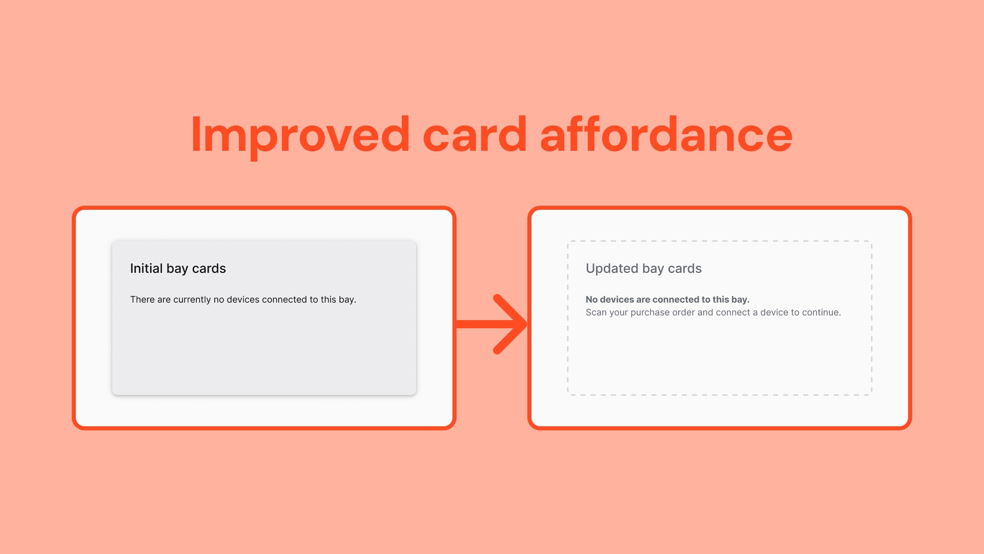
Several participants thought they had to click on the empty bay cards to start the process. So I expanded on the design system to make the cards look less clickable and improved the microcopy.
How it ended
Our limited engineering resources meant that we had to take a slight detour.
To meet a tight deadline, they began by developing a backend update to retrofit the legacy UI while I worked with a new engineer to implement the user interface I designed on our own time.
📚 Extracting further value from my work
The research and improvements I made inspired the rest of the manufacturing facility to optimise other parts of the process and even other production lines!
They started by using my research to enhance the technicians’ workflows and processes, thereby increasing employee satisfaction and efficiency.